Electrical Signal Integrity (SI) testing is a crucial aspect of electronic design validation and verification. It involves ensuring that electrical signals propagate through a system or printed circuit board (PCB) with minimal distortion, noise, and interference. The goal of SI testing is to guarantee that the signal remains intact throughout its journey from source to destination, which is essential for reliable and efficient operation of complex electronic systems.
What is Electrical Signal Integrity?
Electrical Signal Integrity refers to the ability of an electrical signal to maintain its integrity, meaning it retains its original characteristics such as amplitude, frequency, and phase. In other words, SI testing ensures that the signal remains unchanged or minimally affected by various factors during transmission. This includes minimizing reflections, ringing, and overshooting, which can lead to inaccurate results, reduced performance, and even system failure.
Types of Signal Integrity Issues
There are several types of signal integrity issues that can arise in electronic systems:
Reflections: When a signal bounces back from the end of a transmission line, causing multiple copies of the original signal to be present at the receiving end.
Ringing: A phenomenon where a signal overshoots its intended amplitude due to impedance mismatch between the transmitter and receiver.
Overshooting: Excessive voltage or current spikes that can damage components or cause system malfunction.
Key Challenges in Signal Integrity Testing
Signal integrity testing is not without its challenges:
High-frequency signals: As signal speeds increase, SI testing becomes more complex due to increased sensitivity to noise and interference.
Complex PCB layout: Difficult-to-reach areas, multiple layers, and complex routing make it challenging to access and measure signal integrity.
Component variability: Variations in component values and tolerances can affect signal propagation and accuracy.
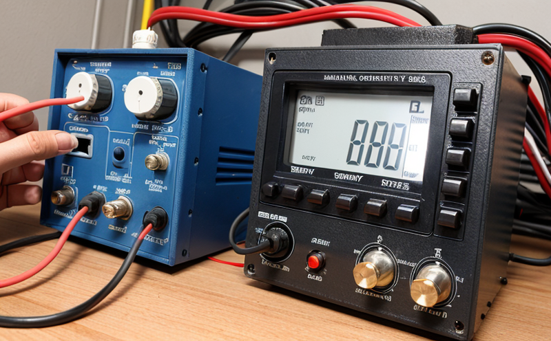
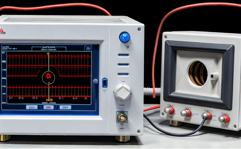
SI Testing Techniques
There are several techniques used for signal integrity testing:
Time-Domain Reflectometry (TDR): Measures signal reflections and provides insights into impedance mismatches and discontinuities.
Vector Network Analysis (VNA): Evaluates the frequency response of a system, including its S-parameters.
Scattering Parameters (S-parameters): Characterize the transfer function between two ports in a network.
Detailed Information on Signal Integrity Testing
Here are some detailed points about signal integrity testing:
Signal Integrity Considerations for High-Speed Digital Signals
High-speed digital signals require careful consideration of SI to ensure reliable transmission. Some key considerations include:
Clock signal distribution: Proper clock signal distribution is crucial to prevent jitter and skew.
Data signal routing: Optimize data signal routing to minimize reflections and ringing.
Power delivery network (PDN): Ensure a robust PDN to maintain stable voltage levels.
Signal Integrity Testing for Analog Signals
Analog signals, such as those found in RF or audio applications, require special attention:
Frequency response: Measure the frequency response of an analog signal to ensure it meets specifications.
Noise floor: Evaluate the noise floor and ensure it is within acceptable limits.
Intermodulation distortion (IMD): Test for IMD to prevent degradation of signal quality.
Signal Integrity Testing in Manufacturing
SI testing plays a critical role in manufacturing:
In-circuit testing (ICT): Perform ICT to detect SI issues early on, reducing the need for costly rework or replacement.
Functional testing: Verify that systems operate as intended, including SI considerations.
Automated test equipment (ATE): Leverage ATE to streamline and accelerate SI testing.
QA Section
Here are some additional questions and answers about signal integrity testing:
What is the difference between Signal Integrity and Power Integrity?
Signal Integrity focuses on ensuring that electrical signals remain intact during transmission, while Power Integrity deals with maintaining stable voltage levels throughout a system.
How do I choose the right SI testing tool for my application?
Consider factors such as frequency range, measurement accuracy, and test fixture requirements when selecting an SI testing tool.
Can signal integrity issues be resolved after PCB layout is complete?
In most cases, changes to the PCB layout are not feasible once it is complete. However, modifications can be made to address specific SI concerns.
What are some common causes of signal integrity issues in high-speed digital systems?
Impedance mismatches, poor ground planes, and inadequate shielding are all common causes of SI issues in high-speed digital systems.
How do I ensure that my SI testing is accurate and reliable?
Calibrate your test equipment regularly, use standardized measurement protocols, and validate your results against industry standards or manufacturer specifications.
Can signal integrity testing be performed at the component level?
Yes, some components can be tested for SI characteristics using specialized test equipment. However, this approach may not always provide a complete picture of system-level SI performance.
In conclusion, electrical signal integrity testing is a critical aspect of electronic design validation and verification. By understanding the challenges and techniques involved in SI testing, designers and engineers can ensure that their systems operate reliably and efficiently. Remember to consider key factors such as high-frequency signals, complex PCB layout, and component variability when approaching SI testing.
---
Additional Resources
For more information on signal integrity testing, refer to these additional resources:
ANSI/TIA-968-A:2002(http://www.ecdirect.com/ansi-tia-968-a-2002/)
IEEE 802.3ba-2010(https://standards.ieee.org/findstds/standard/802.3ba-2010.html)
Signal Integrity: A Guide for PCB Designers and Test Engineers(https://www.cadence.com/content/cadence/us/en/design-resources/pdfs/SI-Guide-for-PCB-Designers.pdf)
By following the guidelines outlined in this article, youll be well on your way to mastering signal integrity testing.