Field Testing for EMI Suppression in High-Density Circuits
Electromagnetic Interference (EMI) has become a significant concern in modern electronic systems, particularly in high-density circuits where compact designs and miniaturization are the norm. With the proliferation of wireless communication devices, automotive electronics, and industrial control systems, the need for effective EMI suppression has reached an all-time high. In this article, we will delve into the world of field testing for EMI suppression in high-density circuits, highlighting the challenges, methodologies, and best practices to ensure reliable and efficient EMI mitigation.
Understanding EMI in High-Density Circuits
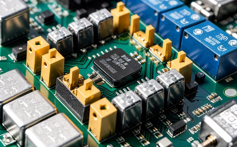
High-density circuits are characterized by their compact design, which often involves densely packed components and complex signal paths. This density leads to increased electromagnetic coupling between components, making it more challenging to control EMI emissions. Additionally, the use of high-speed digital signals, power management systems, and wireless communication modules further exacerbates the EMI issue.
The consequences of inadequate EMI suppression in high-density circuits can be severe:
Reduced system reliability due to interference with other electronic systems
Increased bit error rates and data corruption
System overheating or failure due to excessive electromagnetic radiation
Compliance issues with regulatory requirements, such as FCC Part 15 (USA) or EN 55022 (EU)
Field Testing Methods for EMI Suppression
To ensure effective EMI suppression in high-density circuits, field testing is an essential step in the design and validation process. Several methods can be employed to evaluate EMI performance:
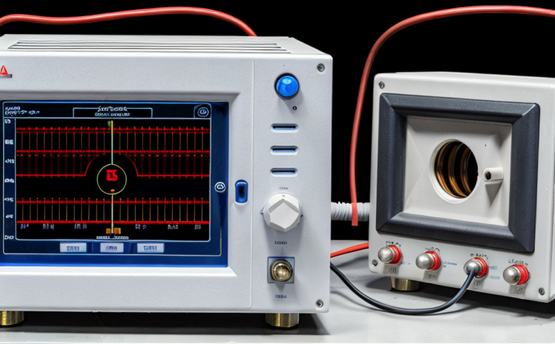
Radiated Emissions (RE): Measuring the electromagnetic radiation emitted by a device or system into free space using a spectrum analyzer and antenna.
Conducted Susceptibility (CS): Testing a devices immunity to conducted interference, typically using a signal generator and a network analyzer.
Field testing for EMI suppression involves several steps:
1.
Design and Preparation: Carefully design the test setup, selecting suitable equipment and calibration procedures.
2.
Pre-Test Inspection: Inspect the circuit board or system before testing to identify any potential issues or defects.
3.
EMI Measurements: Conduct radiated emissions (RE) and conducted susceptibility (CS) tests using calibrated instruments and following established standards (e.g., CISPR 11 for automotive electronics).
4.
Data Analysis: Compare measured EMI levels against regulatory limits and evaluate the effectiveness of EMI suppression techniques used.
5.
Iterative Refining: Based on test results, refine the design to optimize EMI performance.
Detailed Testing Procedures:
Radiated Emissions (RE) Test
Equipment Needed: Spectrum analyzer, antenna, ground plane
Procedure:
1. Mount the device under test (DUT) on a suitable fixture.
2. Connect the DUT to a power source and ensure proper functioning.
3. Use a spectrum analyzer to measure radiated emissions at specified frequencies (e.g., CISPR 11).
4. Compare measured EMI levels against regulatory limits and evaluate effectiveness of EMI suppression techniques used.
Conducted Susceptibility (CS) Test
Equipment Needed: Signal generator, network analyzer, cables
Procedure:
1. Connect the DUT to a signal generator using cables.
2. Use a network analyzer to measure conducted susceptibility at specified frequencies (e.g., CISPR 25).
3. Compare measured EMI levels against regulatory limits and evaluate effectiveness of EMI suppression techniques used.
Best Practices for Effective EMI Suppression
To ensure reliable and efficient EMI mitigation, consider the following best practices:
Design for EMI: Integrate EMI suppression techniques into the circuit design from the outset.
Component Selection: Choose components with low EMI emissions or use EMI-reducing materials (e.g., ferrites).
Shielding and Grounding: Employ effective shielding and grounding techniques to minimize electromagnetic coupling.
EMI Suppression Devices: Utilize proven EMI suppression devices, such as capacitors, inductors, and filters.
Iterative Refining: Continuously refine the design based on test results to optimize EMI performance.
QA Section
1. What are the primary challenges associated with EMI suppression in high-density circuits?
2. What are some common EMI testing methods used in the field?
3. How can I select suitable equipment for EMI testing?
4. What is the significance of design and preparation in field testing for EMI suppression?
5. Can you provide an example of a radiated emissions (RE) test setup?
6. What are some best practices for effective EMI suppression in high-density circuits?
Q1: Primary Challenges Associated with EMI Suppression
The primary challenges associated with EMI suppression in high-density circuits include increased electromagnetic coupling, complex signal paths, and the use of high-speed digital signals.
Q2: Common EMI Testing Methods
Common EMI testing methods include radiated emissions (RE) measurements using a spectrum analyzer and antenna and conducted susceptibility (CS) tests using a signal generator and network analyzer.
Q3: Selecting Suitable Equipment for EMI Testing
When selecting equipment for EMI testing, consider the following factors:
Frequency Range: Choose instruments that can accurately measure EMI levels within the specified frequency range.
Accuracy and Precision: Ensure the selected equipment meets the required accuracy and precision standards (e.g., CISPR 11).
Calibration: Verify the calibration status of each instrument to ensure reliable measurements.
Q4: Design and Preparation in Field Testing
Design and preparation are crucial steps in field testing for EMI suppression. They involve carefully designing the test setup, selecting suitable equipment, and calibrating instruments according to established standards.
Q5: Radiated Emissions (RE) Test Setup Example
Heres an example of a radiated emissions (RE) test setup:
Mount the DUT on a suitable fixture.
Connect the DUT to a power source and ensure proper functioning.
Use a spectrum analyzer to measure radiated emissions at specified frequencies.
Q6: Best Practices for Effective EMI Suppression
Some best practices for effective EMI suppression in high-density circuits include:
Designing for EMI
Selecting components with low EMI emissions
Employing shielding and grounding techniques
Utilizing proven EMI suppression devices
Iterative refining of the design based on test results