Eurolab
-
Lighting and Optical Device Testing-
Optical Sensor Testing-
Measuring Response Time of Optical Sensors
We provide comprehensive solutions designed to help our clients mitigate risks, enhance performance, and excel in key areas such as quality, health & safety, environmental sustainability, and social responsibility.
Discover
For many years, our organization has been operating successfully, boasting modern laboratories that meet international standards. These laboratories are equipped with the latest technology devices and equipment, and we have built a strong team of experienced and trained personnel to operate them.
DiscoverWelcome to Eurolab, your partner in pioneering solutions that encompass every facet of life. We are committed to delivering comprehensive Assurance, Testing, Inspection, and Certification services, empowering our global clientele with the ultimate confidence in their products and processes.
Discover
-
Lighting and Optical Device Testing-
Optical Sensor Testing-
Measuring Response Time of Optical SensorsMeasuring Response Time of Optical Sensors: A Comprehensive Guide
Optical sensors are widely used in various industries for detecting and measuring physical parameters such as temperature, pressure, displacement, and more. The performance of optical sensors can be evaluated using several metrics, one of which is response time. In this article, we will delve into the concept of response time, its importance, and provide a detailed guide on how to measure it.
Response Time: Whats It All About?
The response time of an optical sensor refers to the time taken by the sensor to react or respond to changes in the measured parameter. It is an essential performance characteristic that determines the speed at which the sensor can detect and transmit data. A faster response time enables real-time monitoring, quick decision-making, and improved system efficiency.
There are two types of response times: rise time (tr) and fall time (tf). Rise time represents the time taken by the sensor to reach 90 of its final value after a change in the measured parameter, while fall time is the time taken to drop from 10 to 90 of its original value. The total response time (tR) is typically calculated as the average of rise and fall times.
Measuring Response Time: A Step-by-Step Guide
To measure the response time of an optical sensor, youll need a few basic equipment and a well-defined procedure:
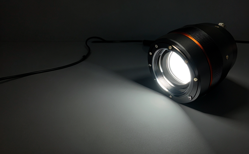
Optical sensor
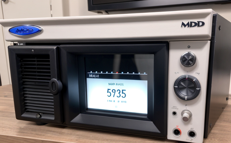
Signal conditioner or amplifier
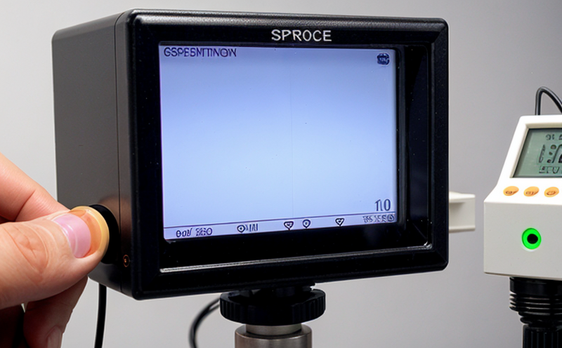
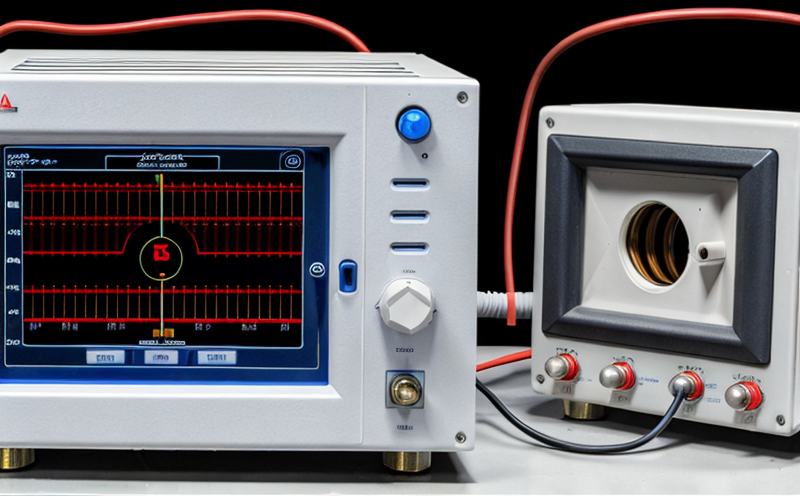
Oscilloscope
Soldering iron (for connecting probes)
Safety glasses and gloves (optional)
Timebase: 1-10 ms/div
Trigger: positive edge trigger (or similar)
Vertical scale: 1-5 V/div
Trigger level: adjust to 50 of peak-to-peak value
3. Connect the signal conditioner or amplifier output to the oscilloscopes input channel.
4. Place a mechanical load (e.g., metal cylinder) near the optical sensor to create a change in the measured parameter.
5. Measure and record the rise time (tr), fall time (tf), and total response time (tR).
Ensure proper grounding of all equipment to prevent electromagnetic interference.
Keep the oscilloscope and signal conditioner amplifier away from heat sources.
Calculating Response Time: A Practical Example
Heres a step-by-step example of calculating the response time of an optical sensor:
Suppose youve measured the following data using an oscilloscope:
Fast-response optical sensors: 1-10 ms
Medium-response optical sensors: 10-100 ms
Slow-response optical sensors: 100-500 ms
Q: How do I ensure accurate measurements when using an oscilloscope?
A: To minimize errors, follow these guidelines:
Use a high-quality oscilloscope with good signal-to-noise ratio.
Ensure proper triggering and grounding.
Keep the oscilloscope and signal conditioner amplifier away from heat sources.
Q: Can I measure response time using other methods besides an oscilloscope?
A: Yes, alternative methods include:
Using a digital multimeter with an oscilloscope-like function
Measuring voltage changes with a data acquisition system
Employing specialized software for measuring response times
Q: What factors can affect the measured response time?
A: Several factors may influence the measured response time:
Environmental conditions (temperature, humidity)
Sensor alignment and mechanical load placement
Signal conditioner amplifier settings and calibration
Q: How do I interpret the measured response time in terms of application performance?
A: When evaluating the measured response time for your specific application, consider the following factors:
Minimum detectable signal (MDS)
Maximum detectable signal (MDS)
Required accuracy and precision
Expected operating conditions
NEBS and Telecommunication Standards
Network Equipment Building System (NEBS) and Telecommunication Standards The Network Equipment Bu...

Environmental Simulation Testing
Environmental Simulation Testing: A Comprehensive Guide In todays world, where technology is rapidl...
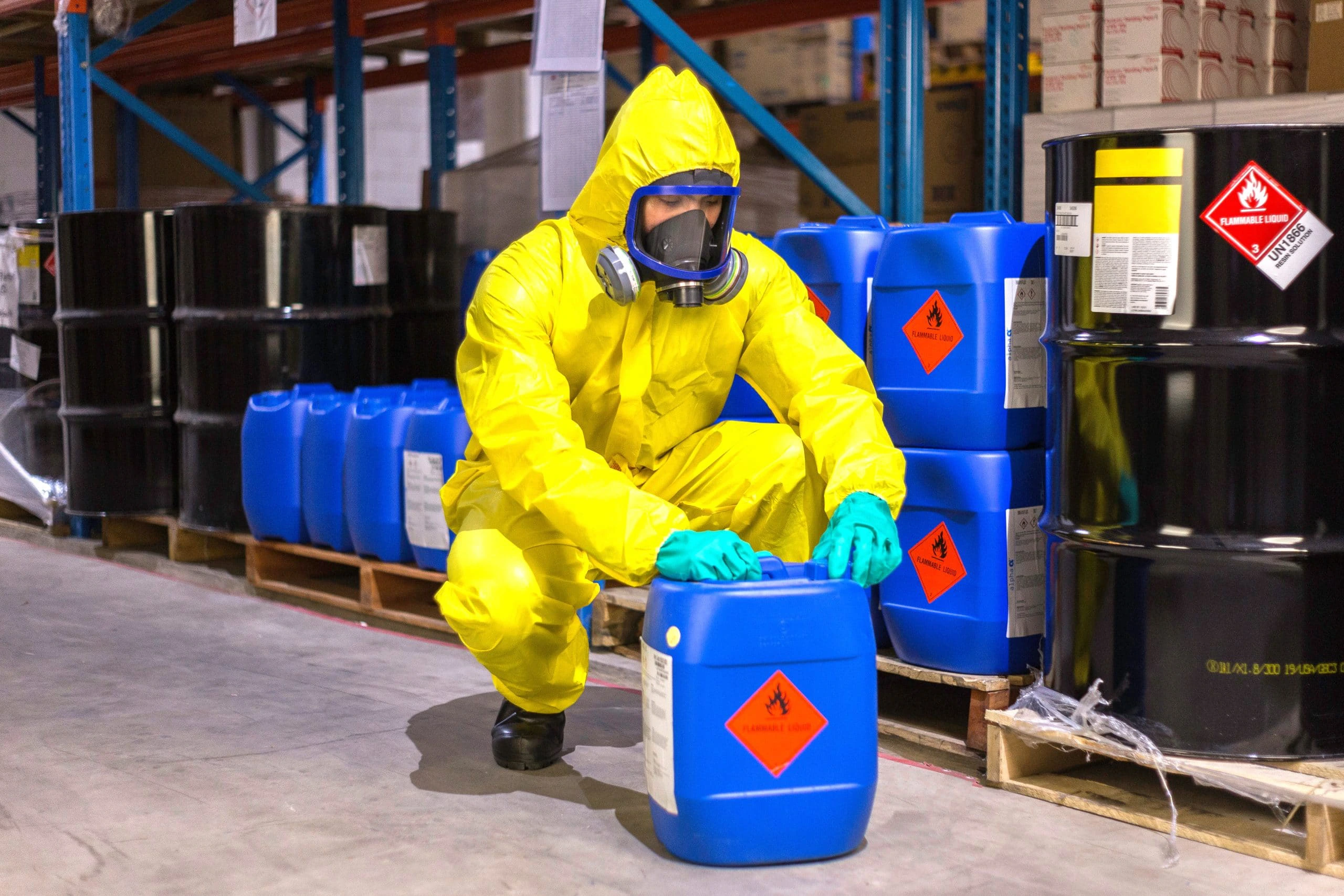
Chemical Safety and Certification
Chemical safety and certification are critical in ensuring the safe management of products and proce...

Transportation and Logistics Certification
Transportation and Logistics Certification: A Comprehensive Guide The transportation and logistics ...
Electromechanical Safety Certification
Electromechanical Safety Certification: Ensuring Compliance and Protecting Lives In todays intercon...

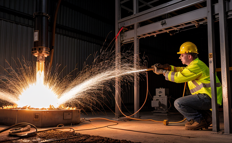
Fire Safety and Prevention Standards
Fire Safety and Prevention Standards: Protecting Lives and Property Fire safety and prevention stan...
Aviation and Aerospace Testing
Aviation and Aerospace Testing: Ensuring Safety and Efficiency The aviation and aerospace industr...

Environmental Impact Assessment
Environmental Impact Assessment: A Comprehensive Guide Environmental Impact Assessment (EIA) is a c...

IT and Data Center Certification
IT and Data Center Certification: Understanding the Importance and Benefits The field of Informatio...

Trade and Government Regulations
Trade and government regulations play a vital role in shaping the global economy. These regulations ...
Electrical and Electromagnetic Testing
Electrical and Electromagnetic Testing: A Comprehensive Guide Introduction Electrical and electrom...

Pharmaceutical Compliance
Pharmaceutical compliance refers to the adherence of pharmaceutical companies and organizations to l...
Lighting and Optical Device Testing
Lighting and Optical Device Testing: Ensuring Performance and Safety Lighting and optical devices a...
MDR Testing and Compliance
MDR Testing and Compliance: A Comprehensive Guide The Medical Device Regulation (MDR) is a comprehe...
Renewable Energy Testing and Standards
Renewable Energy Testing and Standards: Ensuring a Sustainable Future The world is rapidly transiti...
Industrial Equipment Certification
Industrial equipment certification is a critical process that ensures industrial equipment meets spe...
Battery Testing and Safety
Battery Testing and Safety: A Comprehensive Guide As technology continues to advance, battery-power...

Construction and Engineering Compliance
Construction and Engineering Compliance: Ensuring Safety, Quality, and Regulatory Adherence In the ...

Military Equipment Standards
Military Equipment Standards: Ensuring Effectiveness and Safety The use of military equipment is a ...

Hospitality and Tourism Certification
Hospitality and Tourism Certification: Unlocking Opportunities in the Industry The hospitality and ...

Automotive Compliance and Certification
Automotive Compliance and Certification: Ensuring Safety and Efficiency The automotive industry is ...

Consumer Product Safety
Consumer Product Safety: Protecting Consumers from Harmful Products As a consumer, you have the rig...

Energy and Sustainability Standards
In today’s rapidly evolving world, businesses face increasing pressure to meet global energy a...

Agricultural Equipment Certification
Agricultural equipment certification is a process that ensures agricultural machinery meets specific...
Railway Industry Compliance
Railway Industry Compliance: Ensuring Safety and Efficiency The railway industry is a critical comp...

Cosmetic Product Testing
The Complex World of Cosmetic Product Testing The cosmetics industry is a multi-billion-dollar ma...
Pressure Vessels and Installations Testing
Pressure Vessels and Installations Testing Pressure vessels are a critical component of various ind...

Food Safety and Testing
Food Safety and Testing: Ensuring the Quality of Our Food As consumers, we expect our food to be sa...

Product and Retail Standards
Product and Retail Standards: Ensuring Quality and Safety for Consumers In todays competitive marke...
Healthcare and Medical Devices
The Evolution of Healthcare and Medical Devices: Trends, Innovations, and Challenges The healthcare...