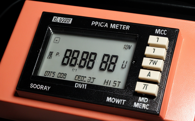
Optical Power Meter Testing: A Comprehensive Guide
As fiber optic communication systems continue to play a vital role in modern technology, ensuring the accuracy of optical power meter testing has become increasingly important. Optical power meters are used to measure the power level of light signals transmitted through fiber optic cables, and incorrect readings can lead to signal degradation, equipment damage, or even complete network failure.
In this article, we will delve into the world of optical power meter testing, exploring the principles behind these devices, their applications, and best practices for accurate measurements. We will also provide detailed explanations of two critical aspects of optical power meter testing in bullet point format.
Principles of Optical Power Meter Testing
Optical power meters measure the power level of light signals transmitted through fiber optic cables using a variety of techniques. The most common method involves converting the incident light into an electrical signal, which is then measured by the device. This conversion can be achieved through photodetectors, such as photodiodes or avalanche photodiodes, which convert the optical signal into an electrical current.
Optical power meters are calibrated to measure a specific range of power levels, typically from -50 dBm (decibels relative to 1 milliwatt) to 20 dBm. The device is designed to provide accurate measurements within this range, but outside of it, errors can occur due to the limitations of the calibration process.
Types of Optical Power Meters
There are several types of optical power meters available, each with its own strengths and weaknesses. Some common types include:
Sweep-based optical power meters: These devices measure the average power of the signal over a specific period by sweeping the detector across the frequency spectrum.
Peak-power optical power meters: These devices measure the peak power of the signal, providing a more accurate representation of the maximum power level.
Scalable optical power meters: These devices are designed for use in high-speed networks and can measure multiple channels simultaneously.
Key Considerations for Optical Power Meter Testing
When performing optical power meter testing, several key considerations must be taken into account to ensure accurate measurements:
Calibration: Regular calibration of the device is essential to maintain accuracy.
Source stability: The light source used to transmit the signal should be stable and consistent.
Fiber length: Longer fibers can lead to signal degradation due to attenuation, which must be accounted for in calculations.
Detailed Explanation 1: Fiber Attenuation
Fiber attenuation refers to the loss of signal strength as it travels through the fiber optic cable. This loss is primarily due to absorption and scattering of light by the material itself. Several factors contribute to fiber attenuation:
Absorption: Light is absorbed by the glass or plastic material, reducing its intensity.
Scattering: Light scatters off imperfections in the material, spreading out and reducing its intensity.
Fiber attenuation can be calculated using the following formula:
Attenuation (dB/km) 10 \
log10(P1/P2)
Where P1 is the input power and P2 is the output power.
Detailed Explanation 2: Polarization Mode Dispersion (PMD)
Polarization mode dispersion (PMD) refers to the spreading of light pulses as they travel through a single-mode fiber. This effect can cause signal degradation, distortion, or even complete loss of signal. Several factors contribute to PMD:
Fiber material: Different materials have varying levels of birefringence, which affects PMD.
Temperature: Changes in temperature can affect the refractive index of the material, leading to changes in PMD.
Cable management: Improper cable management can lead to bending or twisting of the fiber, increasing PMD.
PMD can be measured using various techniques, including:
Optical time-domain reflectometry (OTDR)
Polarization mode dispersion measurement
QA Section
Q: What is the most common application of optical power meter testing?
A: The most common application of optical power meter testing is in fiber optic communication systems, where it is used to measure the power level of light signals transmitted through fiber optic cables.
Q: How often should an optical power meter be calibrated?
A: Optical power meters should be calibrated at least every 6 months or after any maintenance or repairs have been performed on the device.
Q: What are some common errors that can occur during optical power meter testing?
A: Common errors include:
Incorrect calibration
Inconsistent source stability
Fiber length errors
PMD effects
Q: Can I use an optical power meter to measure signal quality?
A: No, optical power meters are designed to measure the power level of light signals only. Signal quality can be measured using other devices, such as bit-error-rate (BER) testers.
Q: How do I choose the right type of optical power meter for my application?
A: Consider factors such as:
Power range: Ensure the device is calibrated to measure within the specified power range.
Accuracy: Choose a device with high accuracy specifications.
Speed: Select a device that can measure signals at the desired speed.
Q: Can I use an optical power meter in conjunction with other testing devices?
A: Yes, optical power meters can be used in combination with other devices, such as OTDRs or BER testers, to provide comprehensive measurements of signal quality and integrity.
By following the guidelines outlined in this article and taking into account the principles and key considerations for optical power meter testing, you can ensure accurate measurements and prevent signal degradation, equipment damage, or complete network failure.