Testing for Crosstalk and Noise in Optical Communication Links
Optical communication links play a crucial role in modern telecommunications, enabling fast and reliable data transfer over long distances. However, with the increasing demand for high-speed and high-capacity data transmission, optical communication links are becoming more complex, making them vulnerable to various types of noise and crosstalk. In this article, we will delve into the importance of testing for crosstalk and noise in optical communication links, the different types of crosstalk and noise, and the techniques used to test and measure these impairments.
Crosstalk is a major concern in optical communication systems as it can lead to signal degradation, bit error rate (BER) increases, and system downtime. Crosstalk occurs when electromagnetic energy from one channel or circuit leaks into another adjacent channel or circuit, causing interference and noise. This phenomenon is more pronounced in high-density optical communication systems where multiple channels are packed closely together.
There are several types of crosstalk that can affect optical communication links:
Direct Crosstalk: Direct crosstalk occurs when the electromagnetic energy from one channel directly affects an adjacent channel.
Adjacent Channel Interference (ACI): ACI occurs when a signal in one channel leaks into another nearby channel, causing interference and noise.
Co-Channel Interference (CCI): CCI is a type of crosstalk where signals in the same frequency band interfere with each other.
Noise is another significant concern in optical communication systems. Noise can be caused by various factors such as thermal noise, shot noise, dark current, and fiber nonlinearities. Thermal noise occurs due to the random movement of electrons in a circuit, while shot noise is caused by the random arrival of photons at a detector. Dark current is the leakage current that flows through a photodiode even when no light is incident on it.
Types of Noise:
Thermal Noise: Thermal noise is caused by the random movement of electrons in a circuit.
Shot Noise: Shot noise is caused by the random arrival of photons at a detector.
Dark Current: Dark current is the leakage current that flows through a photodiode even when no light is incident on it.
Fiber Nonlinearities: Fiber nonlinearities occur due to the Kerr effect, where the refractive index of the fiber changes with intensity.
Testing and Measurement Techniques:
To test for crosstalk and noise in optical communication links, various techniques can be employed. These include:
1.
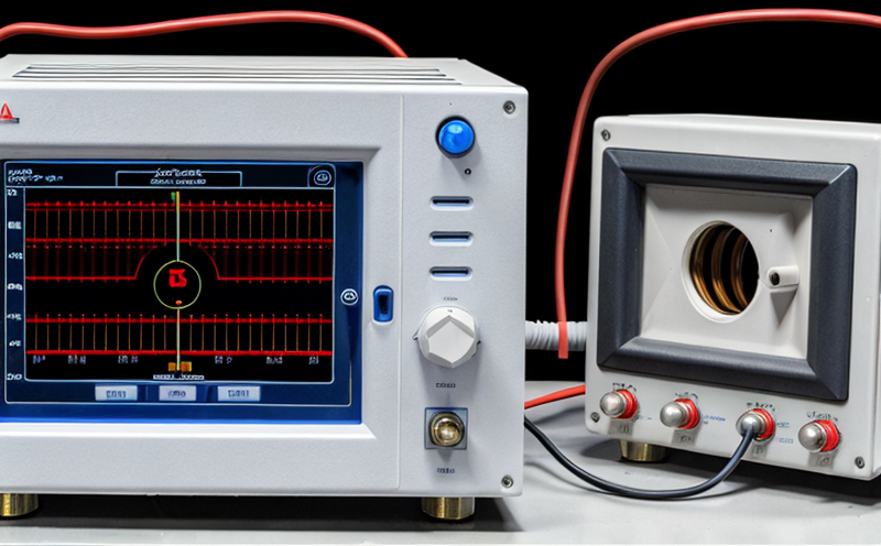
Optical Spectrum Analyzer (OSA): An OSA is used to measure the spectral power density of a signal.
2.
Power Meter: A power meter measures the average power of an optical signal.
3.
Spectrum Analyzer: A spectrum analyzer measures the frequency content of an electrical or optical signal.
4.
Vector Network Analyzer (VNA): A VNA is used to measure the scattering parameters of a device under test.
To further understand crosstalk and noise in optical communication links, lets break down some key concepts in bullet points:
Crosstalk Measurement Techniques
Direct Detection Method: The direct detection method involves measuring the power of the signal at each channel.
Coherent Detection Method: The coherent detection method uses a laser to measure the phase and amplitude of the signal.
Interferometric Method: The interferometric method uses an optical interferometer to measure the crosstalk between channels.
Noise Measurement Techniques
Spectral Analysis: Spectral analysis is used to measure the power spectral density of the noise.
Time-Domain Analysis: Time-domain analysis involves measuring the time-domain characteristics of the noise.
Frequency-Domain Analysis: Frequency-domain analysis involves measuring the frequency-domain characteristics of the noise.
QA Section
Q: What are the effects of crosstalk on optical communication systems?
A: Crosstalk can lead to signal degradation, bit error rate (BER) increases, and system downtime. It can also cause interference between channels, reducing the overall capacity and efficiency of the system.
Q: How is crosstalk typically measured in optical communication links?
A: C Crosstalk is typically measured using techniques such as direct detection, coherent detection, or interferometric methods.
Q: What are some common sources of noise in optical communication systems?
A: Thermal noise, shot noise, dark current, and fiber nonlinearities are some common sources of noise in optical communication systems.
Q: How can crosstalk be minimized in high-density optical communication systems?
A: Minimizing the distance between channels, using crosstalk-reducing optical fibers, and employing advanced modulation schemes can help minimize crosstalk in high-density optical communication systems.
Q: What is the role of an Optical Spectrum Analyzer (OSA) in testing for noise and crosstalk?
A: An OSA measures the spectral power density of a signal, allowing technicians to identify and quantify sources of noise and crosstalk.