Testing Grounding Systems for Electrical Safety: A Comprehensive Guide
Introduction
Grounding systems are a critical component of electrical safety in buildings and industrial settings. They provide a safe path to earth for fault currents, helping to prevent shock and electrocution. However, grounding systems can fail or become inadequate over time due to various factors such as corrosion, damage, or incorrect installation. Therefore, it is essential to regularly test and inspect grounding systems to ensure they are functioning correctly.
Types of Grounding Systems
There are several types of grounding systems used in buildings and industrial settings, including:
Solidly grounded systems: These systems connect the electrical panel or distribution board directly to earth.
Unbalanced four-wire delta systems: These systems use a neutral conductor that is separated from the phase conductors by insulation.
Wye-connected systems: These systems use three-phase conductors connected to a common point, with a separate neutral conductor.
Testing Grounding Systems
Grounding system testing involves verifying that the grounding system is functioning correctly and providing a safe path to earth. The following steps should be taken when testing a grounding system:
1. Inspect the grounding system for any signs of damage or corrosion.
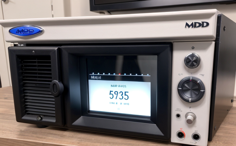
2. Measure the resistance of the grounding system using a grounding resistance tester (GRT).
3. Check the continuity of the grounding conductor using a multimeter.
4. Verify that the grounding system is connected to earth.
Measuring Grounding Resistance
Grounding resistance testing is used to determine the resistance of the grounding system to earth. This measurement can be taken at various points in the system, including:
The service entrance
The electrical panel or distribution board
Equipment and appliances
Grounding rods and electrodes
The GRT measures the voltage drop across a known resistance, which is then used to calculate the actual resistance of the grounding system. A low reading indicates good grounding, while high readings may indicate poor grounding.
Types of Fault Currents
Fault currents are created when there is a short circuit or ground fault in an electrical circuit. There are two types of fault currents:
Single-phase-to-ground (SPG) faults: These occur when a single phase conductor touches the earth.
Three-phase-to-ground (3PG) faults: These occur when all three phase conductors touch the earth.
Testing for Fault Currents
Fault current testing is used to verify that the grounding system can handle fault currents. The following steps should be taken:
1. Identify the type of fault current likely to occur in the circuit.
2. Determine the maximum fault current rating of the grounding system.
3. Use a fault current tester to measure the actual fault current.
Key Considerations for Testing Grounding Systems
Safety: When testing grounding systems, safety should be the top priority. Ensure that all personnel involved in the testing process are properly trained and equipped with personal protective equipment (PPE).
Accuracy: Grounding system testing requires accurate measurements to ensure that the system is functioning correctly. Use calibrated equipment and follow established procedures.
Frequency: Regular testing of grounding systems should be performed to identify any issues before they become safety hazards.
Detailed Information on Testing Grounding Systems
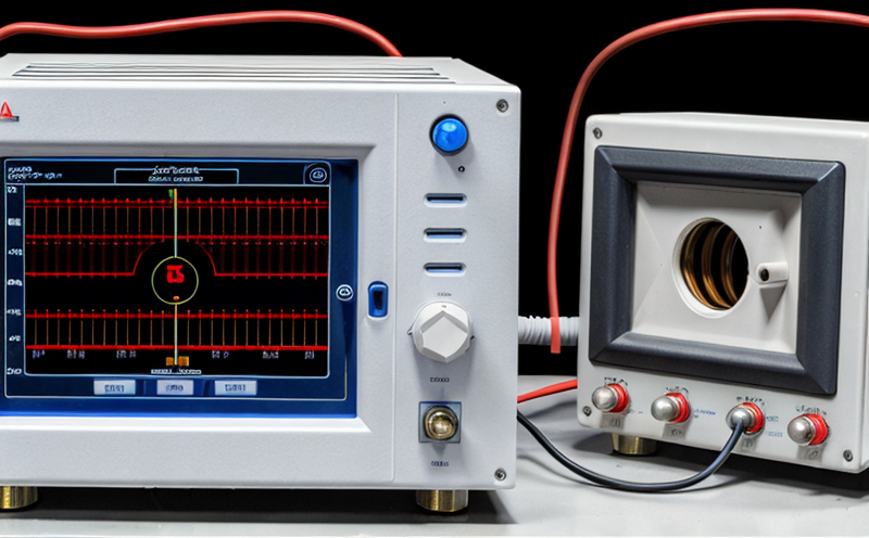
What is a grounding resistance tester (GRT)?
A GRT measures the voltage drop across a known resistance, which is then used to calculate the actual resistance of the grounding system. This device helps determine whether the grounding system can safely handle fault currents.
What are the advantages and disadvantages of using an unbalanced four-wire delta system?
Advantages:
More flexible than other systems
Can be used in a variety of applications
Disadvantages:
Requires more complex installation procedures
May experience higher voltage drops due to the separation between neutral and phase conductors
What is the purpose of testing for fault currents?
Fault current testing verifies that the grounding system can handle the maximum possible fault current, ensuring electrical safety.
QA Section
Q: What are some common reasons for poor grounding in a building or industrial setting?
A: Poor grounding can occur due to various factors, including corrosion on grounding electrodes, incorrect installation of grounding conductors, and excessive resistance in the grounding system.
Q: Can I use any type of wire for grounding purposes?
A: No. Grounding wires must be specifically designed for grounding applications and meet relevant safety standards.
Q: How often should I test my grounding system?
A: Regular testing is essential to ensure electrical safety. Testing frequency will depend on the type of application, but its recommended to test at least annually.
Q: What is the ideal resistance value for a grounding system?
A: The American National Standards Institute (ANSI) recommends a maximum grounding resistance of 1 ohm for most applications.
Q: Can I use a multimeter for testing grounding systems?
A: While a multimeter can be used to measure continuity and voltage, it is not suitable for measuring grounding resistance. A GRT should be used instead.
Q: How do I choose the right fault current tester?
A: When selecting a fault current tester, consider factors such as accuracy, measurement range, and calibration requirements.
Q: Are there any specific safety precautions to take when testing grounding systems?
A: Yes. Ensure that all personnel involved in the testing process are properly trained and equipped with PPE. Follow established procedures and use calibrated equipment.
Conclusion
Grounding system testing is a critical aspect of electrical safety in buildings and industrial settings. Regular inspections and testing can help identify potential issues before they become hazards. This guide has provided an overview of grounding systems, types of fault currents, and the importance of accurate measurement using specialized equipment. By following established procedures and guidelines, personnel can ensure that their grounding system is functioning correctly, providing a safe path to earth for fault currents.
Sources
National Electric Code (NEC) standards
American National Standards Institute (ANSI)
Grounding Resistance Testing Handbook