Testing Interference Suppression in Electrical Circuits
Electrical interference, also known as electromagnetic interference (EMI), can cause malfunctions or damage to electronic devices connected to electrical circuits. In todays complex electronic systems, it is essential to ensure that electrical circuits are designed and built with adequate interference suppression capabilities. Testing interference suppression in electrical circuits requires a thorough understanding of the principles involved and specialized equipment.
Understanding Interference Suppression
Interference suppression refers to the techniques used to prevent or minimize electromagnetic interference (EMI) in electrical circuits. EMI can be caused by various sources, including switching power supplies, fluorescent lighting, radio transmitters, and other electronic devices that generate high-frequency electromagnetic fields. These fields can induce unwanted voltages and currents on circuit boards, causing malfunctions or damage to sensitive components.
To suppress EMI, electrical circuits are designed with various components and techniques. Some common methods include:
Shielding: Using conductive materials to enclose a circuit or component, preventing electromagnetic fields from entering or leaving the shielded area.
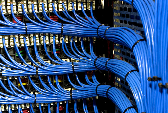
Grounding: Connecting sensitive components to a stable ground point to prevent voltage differences between them and other parts of the circuit.
Decoupling capacitors: Placing small value capacitors in parallel with sensitive components to filter out high-frequency noise.
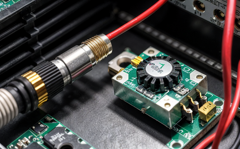
Ferrite beads: Using ferrite materials to absorb or dissipate electromagnetic energy.
Testing Interference Suppression Techniques
Testing interference suppression techniques requires specialized equipment and a thorough understanding of the principles involved. Some common methods include:
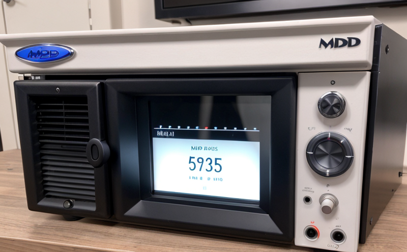
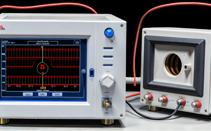
Spectrum analyzer: Measuring the frequency spectrum of EMI emissions from a circuit or device.
EMC (Electromagnetic Compatibility) test chamber: A controlled environment for testing EMI immunity of devices connected to electrical circuits.
Rigorous inspection and testing: Visual inspection of components, wiring, and enclosures for signs of EMI-related damage or defects.
Detailed Testing Procedures
Here are two detailed paragraphs in bullet point format with explanations or information:
Testing Shielding Effectiveness
To test shielding effectiveness, follow these steps:
Identify the shielded area: Determine which components or circuits require shielding based on design requirements and analysis of EMI emissions.
Measure pre-shielding data: Use a spectrum analyzer to measure the frequency spectrum of EMI emissions from the unshielded circuit or device.
Apply shielding material: Wrap or enclose the shielded area with conductive materials, ensuring proper contact and connection to ground points.
Measure post-shielding data: Repeat the measurement using the spectrum analyzer, comparing results before and after applying shielding.
Testing Grounding Effectiveness
To test grounding effectiveness, follow these steps:
Identify sensitive components: Determine which components are most susceptible to EMI-related malfunctions or damage.
Measure pre-grounding data: Use a multimeter to measure the voltage difference between sensitive components and other parts of the circuit.
Connect components to ground: Ensure that all sensitive components are properly connected to a stable ground point, using suitable wiring and connectors.
Measure post-grounding data: Repeat the measurement using the multimeter, comparing results before and after applying grounding.
Testing Decoupling Capacitor Effectiveness
To test decoupling capacitor effectiveness, follow these steps:
Identify sensitive components: Determine which components are most susceptible to EMI-related malfunctions or damage.
Measure pre-decoupling data: Use a spectrum analyzer to measure the frequency spectrum of EMI emissions from the unfiltered circuit or device.
Apply decoupling capacitors: Place small value capacitors in parallel with sensitive components, ensuring proper connection and orientation.
Measure post-decoupling data: Repeat the measurement using the spectrum analyzer, comparing results before and after applying decoupling.
Testing Ferrite Bead Effectiveness
To test ferrite bead effectiveness, follow these steps:
Identify high-frequency noise sources: Determine which components or circuits are generating high-frequency EMI emissions.
Measure pre-ferrite data: Use a spectrum analyzer to measure the frequency spectrum of EMI emissions from the unfiltered circuit or device.
Apply ferrite beads: Wrap or insert ferrite materials near the noise source, ensuring proper contact and connection to ground points.
Measure post-ferrite data: Repeat the measurement using the spectrum analyzer, comparing results before and after applying ferrite.
QA Section
Q1: What are the common sources of EMI in electrical circuits?
A1: Common sources of EMI include switching power supplies, fluorescent lighting, radio transmitters, and other electronic devices that generate high-frequency electromagnetic fields.
Q2: How do shielding materials absorb or dissipate electromagnetic energy?
A2: Shielding materials can absorb or dissipate electromagnetic energy through various mechanisms, including conduction, diffusion, and absorption. Ferrite materials, in particular, are designed to absorb high-frequency electromagnetic energy.
Q3: Why is it essential to test interference suppression techniques in electrical circuits?
A3: Testing interference suppression techniques ensures that electrical circuits meet design requirements for EMI immunity, preventing malfunctions or damage to sensitive components.
Q4: What are the advantages of using decoupling capacitors in electrical circuits?
A4: Decoupling capacitors can filter out high-frequency noise and reduce voltage differences between sensitive components and other parts of the circuit.
Q5: How do ferrite beads compare to other EMI suppression techniques?
A5: Ferrite beads are a cost-effective and easy-to-implement solution for suppressing high-frequency EMI emissions. However, their effectiveness depends on the specific application and noise source characteristics.
Conclusion
Testing interference suppression in electrical circuits requires a thorough understanding of the principles involved and specialized equipment. By identifying common sources of EMI, applying shielding materials, grounding components, decoupling capacitors, and ferrite beads, designers can ensure that electrical circuits meet design requirements for EMI immunity. Regular testing and maintenance are essential to maintaining optimal performance and preventing malfunctions or damage.