Eurolab
-
Electrical and Electromagnetic Testing-
Advanced Circuit Testing-
Testing Signal Flow in Complex Electrical Circuits
We provide comprehensive solutions designed to help our clients mitigate risks, enhance performance, and excel in key areas such as quality, health & safety, environmental sustainability, and social responsibility.
Discover
For many years, our organization has been operating successfully, boasting modern laboratories that meet international standards. These laboratories are equipped with the latest technology devices and equipment, and we have built a strong team of experienced and trained personnel to operate them.
DiscoverWelcome to Eurolab, your partner in pioneering solutions that encompass every facet of life. We are committed to delivering comprehensive Assurance, Testing, Inspection, and Certification services, empowering our global clientele with the ultimate confidence in their products and processes.
Discover
-
Electrical and Electromagnetic Testing-
Advanced Circuit Testing-
Testing Signal Flow in Complex Electrical CircuitsTesting Signal Flow in Complex Electrical Circuits
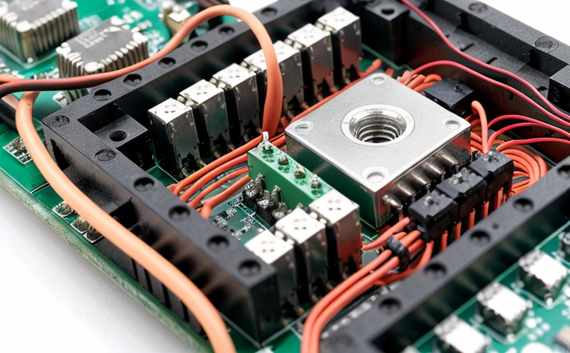
Complex electrical circuits are a vital part of modern electronics, and ensuring their proper functioning is crucial for efficient and reliable operation. One critical aspect of circuit design and testing is signal flow analysis, which involves tracing the path of electric current through the circuit to identify any potential issues or bottlenecks. In this article, we will delve into the world of signal flow testing in complex electrical circuits, exploring the concepts, techniques, and best practices for effective testing.
Understanding Signal Flow
Signal flow refers to the movement of electric current through a circuit from one point to another. It is a critical aspect of circuit design, as any disruptions or blockages can cause system malfunctions or failures. To test signal flow in complex electrical circuits, engineers use specialized tools and techniques that allow them to visualize and analyze the flow of current.
Components Involved in Signal Flow
The following components are typically involved in signal flow:
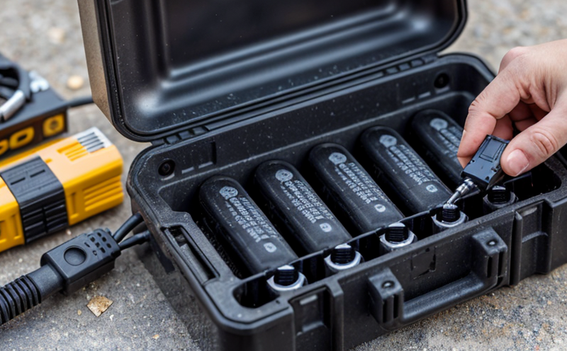
Power Sources: The primary source of electric power, such as batteries, generators, or mains supply.
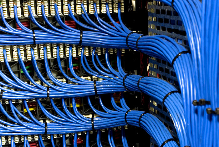
Conductors: Wires, cables, or other materials that allow the flow of electric current.
Resistors: Components that resist the flow of electric current, used to control voltage and current levels.
Capacitors: Components that store electric charge, used for filtering, coupling, and decoupling.
Inductors: Components that store magnetic energy, used for filtering, coupling, and inductance.
Semiconductors: Devices made from materials with electrical conductivity between conductors and insulators, such as transistors and diodes.
Signal Flow Analysis Techniques
There are several techniques used to analyze signal flow in complex electrical circuits:
Visual Inspection: A visual examination of the circuits wiring and components to identify any potential issues or bottlenecks.
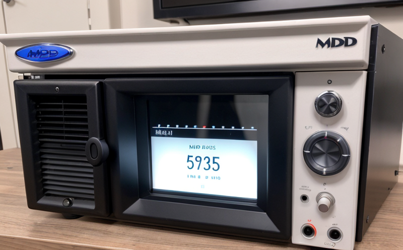
Multimeter Testing: The use of multimeters to measure voltage, current, and resistance levels throughout the circuit.
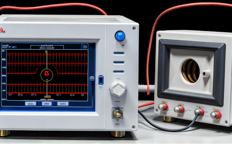
Signal Tracing: The process of tracing the signal flow through the circuit using specialized tools such as oscilloscopes and logic analyzers.
Step-by-Step Guide to Signal Flow Testing
Here is a step-by-step guide to signal flow testing in complex electrical circuits:
1. Identify the Circuit Path: Determine the desired path of electric current through the circuit.
2. Analyze Power Sources: Verify that power sources are functioning correctly and providing sufficient voltage and current levels.
3. Measure Voltage and Current: Use multimeters to measure voltage and current levels at key points throughout the circuit.
4. Check for Short Circuits: Identify any potential short circuits or electrical connections that could cause system malfunctions.
5. Verify Signal Flow: Use signal tracing techniques to confirm that signals are flowing correctly through the circuit.
Troubleshooting Common Issues
Here are some common issues and their solutions when it comes to signal flow testing:
Low Voltage Levels: Check for faulty power sources, resistors, or capacitors.
High Current Levels: Verify correct resistor values and check for short circuits.
Signal Loss: Analyze the circuits wiring and components for any potential bottlenecks or blockages.
QA Section
Here are some frequently asked questions related to signal flow testing in complex electrical circuits:
Q: What is the most common issue when it comes to signal flow testing?
A: The most common issue is low voltage levels, often caused by faulty power sources, resistors, or capacitors.
Q: How can I determine if a circuit has a short circuit?
A: Use multimeters to measure voltage and current levels at key points throughout the circuit. Check for any unusual readings or signs of electrical connections that could cause system malfunctions.
Q: What are some common tools used for signal flow testing?
A: Multimeters, oscilloscopes, logic analyzers, and signal generators are commonly used to analyze signal flow in complex electrical circuits.
Q: How often should I test signal flow in a circuit?
A: It is recommended to perform regular signal flow tests (e.g., every 6-12 months) as part of routine maintenance to ensure system reliability and efficiency.
Q: What are some best practices for testing signal flow?
A: Some best practices include:
Using specialized tools and techniques for accurate analysis.
Documenting test results and findings for future reference.
Continuously monitoring and updating the circuit design based on test results.
By following these steps, guidelines, and best practices, engineers can effectively test signal flow in complex electrical circuits, ensuring efficient operation and minimizing system failures.

Trade and Government Regulations
Trade and government regulations play a vital role in shaping the global economy. These regulations ...
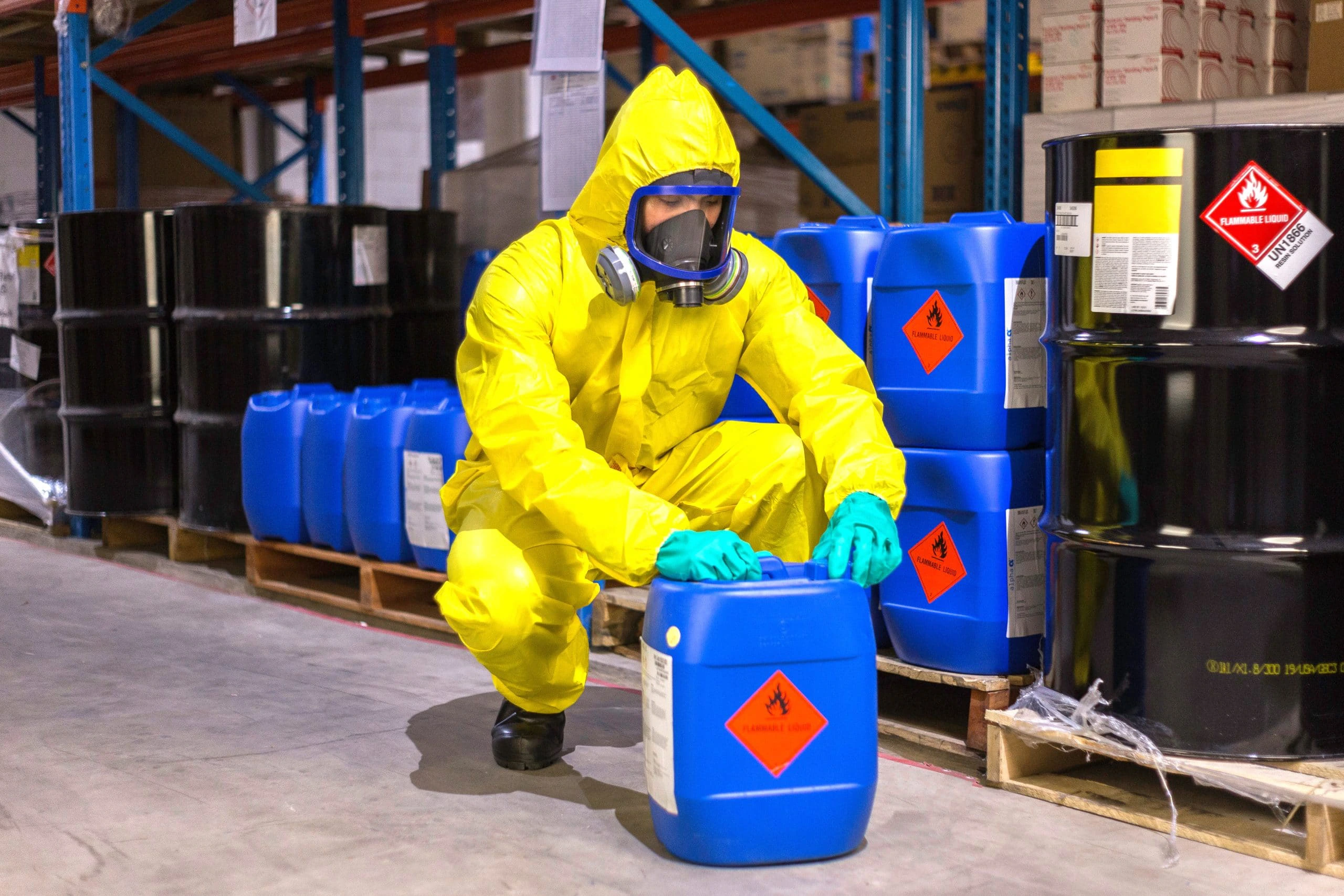
Chemical Safety and Certification
Chemical safety and certification are critical in ensuring the safe management of products and proce...

Pharmaceutical Compliance
Pharmaceutical compliance refers to the adherence of pharmaceutical companies and organizations to l...

Product and Retail Standards
Product and Retail Standards: Ensuring Quality and Safety for Consumers In todays competitive marke...

Agricultural Equipment Certification
Agricultural equipment certification is a process that ensures agricultural machinery meets specific...
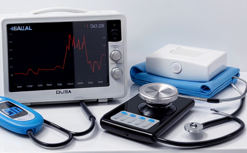
Healthcare and Medical Devices
The Evolution of Healthcare and Medical Devices: Trends, Innovations, and Challenges The healthcare...
Electrical and Electromagnetic Testing
Electrical and Electromagnetic Testing: A Comprehensive Guide Introduction Electrical and electrom...

Consumer Product Safety
Consumer Product Safety: Protecting Consumers from Harmful Products As a consumer, you have the rig...

Automotive Compliance and Certification
Automotive Compliance and Certification: Ensuring Safety and Efficiency The automotive industry is ...

Military Equipment Standards
Military Equipment Standards: Ensuring Effectiveness and Safety The use of military equipment is a ...

Hospitality and Tourism Certification
Hospitality and Tourism Certification: Unlocking Opportunities in the Industry The hospitality and ...

Fire Safety and Prevention Standards
Fire Safety and Prevention Standards: Protecting Lives and Property Fire safety and prevention stan...
Renewable Energy Testing and Standards
Renewable Energy Testing and Standards: Ensuring a Sustainable Future The world is rapidly transiti...

Cosmetic Product Testing
The Complex World of Cosmetic Product Testing The cosmetics industry is a multi-billion-dollar ma...
Pressure Vessels and Installations Testing
Pressure Vessels and Installations Testing Pressure vessels are a critical component of various ind...

Environmental Simulation Testing
Environmental Simulation Testing: A Comprehensive Guide In todays world, where technology is rapidl...

Electromechanical Safety Certification
Electromechanical Safety Certification: Ensuring Compliance and Protecting Lives In todays intercon...
Lighting and Optical Device Testing
Lighting and Optical Device Testing: Ensuring Performance and Safety Lighting and optical devices a...
Industrial Equipment Certification
Industrial equipment certification is a critical process that ensures industrial equipment meets spe...

Transportation and Logistics Certification
Transportation and Logistics Certification: A Comprehensive Guide The transportation and logistics ...
MDR Testing and Compliance
MDR Testing and Compliance: A Comprehensive Guide The Medical Device Regulation (MDR) is a comprehe...

Energy and Sustainability Standards
In today’s rapidly evolving world, businesses face increasing pressure to meet global energy a...

Environmental Impact Assessment
Environmental Impact Assessment: A Comprehensive Guide Environmental Impact Assessment (EIA) is a c...

IT and Data Center Certification
IT and Data Center Certification: Understanding the Importance and Benefits The field of Informatio...
NEBS and Telecommunication Standards
Network Equipment Building System (NEBS) and Telecommunication Standards The Network Equipment Bu...
Railway Industry Compliance
Railway Industry Compliance: Ensuring Safety and Efficiency The railway industry is a critical comp...
Battery Testing and Safety
Battery Testing and Safety: A Comprehensive Guide As technology continues to advance, battery-power...

Food Safety and Testing
Food Safety and Testing: Ensuring the Quality of Our Food As consumers, we expect our food to be sa...

Construction and Engineering Compliance
Construction and Engineering Compliance: Ensuring Safety, Quality, and Regulatory Adherence In the ...

Aviation and Aerospace Testing
Aviation and Aerospace Testing: Ensuring Safety and Efficiency The aviation and aerospace industr...