Testing the Integrity of Grounding Electrode Systems
Introduction
The grounding electrode system (GES) is a critical component of electrical power systems, designed to protect people and equipment from electrical shock. A well-designed and properly installed GES can prevent electrical discharges from occurring between conductors and the ground, thereby minimizing the risk of electric shock. However, over time, the integrity of the GES may be compromised due to various factors such as corrosion, soil conditions, or inadequate installation practices.
Conducting a thorough testing program is essential to ensure that the GES remains effective in providing protection against electrical shock. This article provides an overview of the principles and procedures for testing the integrity of grounding electrode systems, including detailed explanations of key concepts and considerations.
Understanding Grounding Electrode Systems
Grounding electrode systems are designed to provide a safe path to ground for electrical currents. The system typically consists of several components, including:
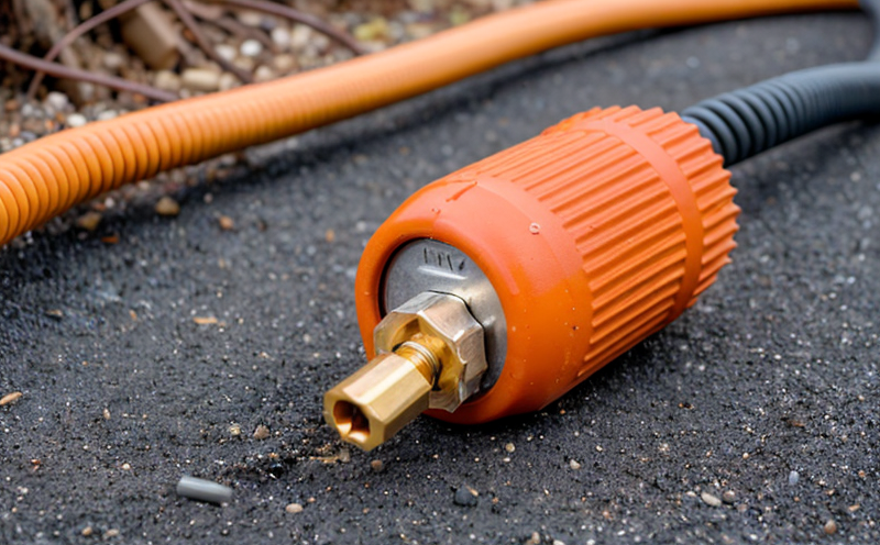
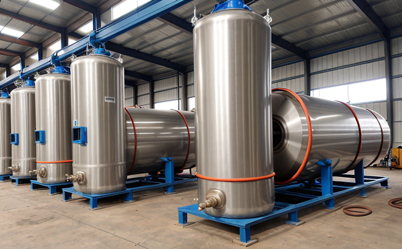
Grounding electrodes: These are metallic objects buried in the earth that serve as the primary means of grounding the power distribution system.
Service conductors: These are the wires that carry electricity from the power source to the building or structure being served.
Bonding jumpers: These are cables or rods used to connect the service conductors and grounding electrodes, ensuring a low-impedance path to ground.
Grounding grid systems: These are networks of underground electrodes that provide additional grounding capability.
Testing Methods for Grounding Electrode Systems
There are several methods available for testing the integrity of GES. The most common techniques include:
Earth resistance measurements: This method involves measuring the electrical resistance between the grounding electrode and a remote reference point, typically a metal rod driven into the earth.
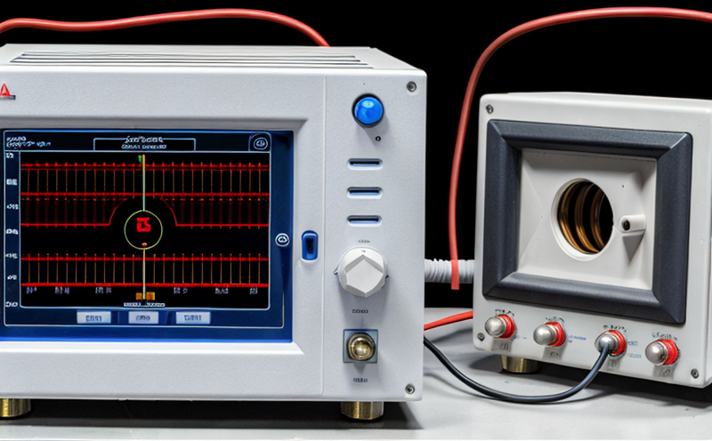
Ground potential rise (GPR) tests: These tests measure the voltage at which the grounding electrode system rises above ground potential in response to an electrical fault.
Electrical discharge testing (EDT): This method simulates a lightning strike by injecting high-energy discharges into the GES, allowing for evaluation of its performance under extreme conditions.
Detailed Explanation of Earth Resistance Measurements
Earth resistance measurements are used to determine the ability of the grounding electrode system to provide a low-impedance path to ground. The measurement involves driving an earth rod or plate into the earth at a distance from the grounding electrodes being tested, and then measuring the electrical potential difference between the two points.
Here is a step-by-step guide to conducting earth resistance measurements:
Select the testing site: Choose a location with minimal interference from nearby structures or other factors that could affect the accuracy of the measurement.
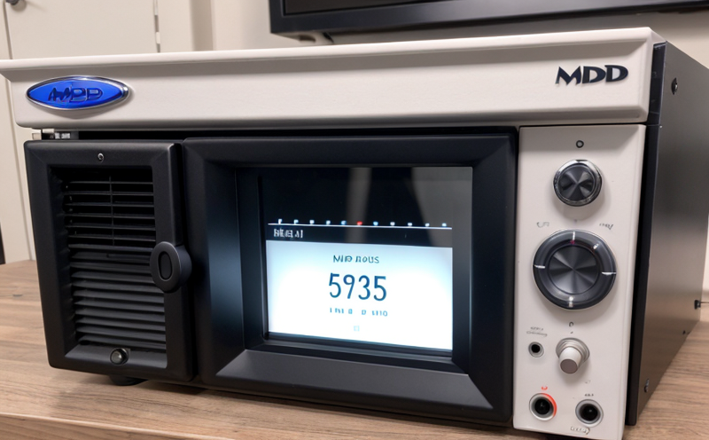
Prepare the test equipment: Connect the earth rod or plate to the measuring instrument and ensure all connections are secure.
Measure the initial earth resistance: Record the reading on the measuring instrument, taking care to note any adjustments made during the testing process.
Apply a DC current: Apply a small DC current (usually around 10-20 amps) through the earth rod or plate to simulate the flow of fault currents.
Measure the final earth resistance: Record the reading on the measuring instrument after applying the DC current, taking care to note any changes in the measurement.
Detailed Explanation of Ground Potential Rise (GPR) Tests
Ground potential rise tests measure the voltage at which the grounding electrode system rises above ground potential in response to an electrical fault. This method is particularly useful for assessing the performance of GES under severe conditions.
Here is a step-by-step guide to conducting GPR tests:
Set up the test equipment: Connect the measuring instrument and other necessary devices, taking care to ensure all connections are secure.
Apply a DC current: Apply a small DC current (usually around 10-20 amps) through the grounding electrode system to simulate the flow of fault currents.
Measure the ground potential rise: Record the reading on the measuring instrument after applying the DC current, noting any changes in the measurement.
Increase the DC current: Gradually increase the DC current to a level that represents the maximum fault current expected at the site.
Monitor and record the GPR voltage: Continue monitoring and recording the GPR voltage until it reaches a predetermined level (usually around 20-50 volts).
QA Section
Q: What is the recommended frequency for testing grounding electrode systems?
A: The American National Standards Institute (ANSI) recommends that GES be tested at least once every five years. However, more frequent testing may be necessary in areas with high soil moisture or where corrosive substances are present.
Q: How do I choose the right test equipment for conducting earth resistance measurements?
A: When selecting test equipment for earth resistance measurements, look for devices that meet the requirements of ANSI C2-2007 and IEEE 142-2007. Consider factors such as accuracy, range, and portability when making your selection.
Q: What are some common issues to watch out for during GES testing?
A: Some common issues to be aware of during GES testing include:
Soil conditions (e.g., high moisture content or presence of corrosive substances)
Inadequate grounding electrode spacing
Poor bonding between service conductors and grounding electrodes
Q: Can I use a ground potential rise test to evaluate the performance of a grounding grid system?
A: While GPR tests can provide valuable information about the performance of a GES, they may not be suitable for evaluating grounding grid systems. Grids often have multiple electrodes connected together, which can make it difficult to interpret GPR readings.
Q: How do I calculate the required test current for earth resistance measurements?
A: The recommended test current for earth resistance measurements is typically 1-10 amps, depending on the system being tested and the specific requirements of the testing standard. Always consult with the relevant testing standards (e.g., ANSI C2-2007) before conducting any testing.
Q: What are some common misconceptions about grounding electrode systems?
A: Some common misconceptions about GES include:
That a single grounding electrode is sufficient to protect an entire building or structure
That grounding electrode spacing can be determined by simply dividing the systems fault current by 1 amp per square foot
That all GES require testing at regular intervals
Conclusion
Testing the integrity of grounding electrode systems is essential for ensuring that electrical power systems are safe and reliable. By understanding key concepts such as earth resistance measurements and ground potential rise tests, users can take steps to prevent electrical discharges from occurring between conductors and the ground. Remember to consult relevant testing standards and consider factors like soil conditions and bonding practices when conducting GES testing.