Testing Electrical Signal Loss in Long Cable Runs
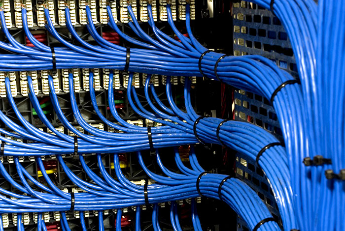
Long cable runs are a common feature of many industrial and commercial applications, from power transmission lines to Ethernet cables connecting network devices. However, as cable length increases, signal loss becomes a significant concern. This article will provide an overview of the causes and effects of electrical signal loss in long cable runs, along with methods for testing and minimizing signal degradation.
Causes of Signal Loss
Signal loss occurs when an electrical signal weakens or attenuates as it travels through a conductor, such as a cable. There are several reasons why this happens:
Resistance: As the signal flows through the conductor, it encounters resistance from the material itself, which converts some of the energy into heat.
Inductance: The conductors inductance causes the signal to be slowed down and altered as it travels through the cable.
Capacitance: Capacitive coupling between different parts of the circuit can cause unwanted energy storage and loss of high-frequency components.
Dielectric Loss: The insulation material surrounding the conductor can lose energy due to dielectric absorption, particularly at higher frequencies.
Effects of Signal Loss
Signal loss can have significant consequences for industrial and commercial applications. Some of the effects include:
Data Corruption: In digital systems, signal loss can cause data corruption or errors in transmission.
Power Outage: In power transmission lines, signal loss can lead to a complete power outage if the voltage drops below a certain threshold.
Equipment Damage: Excessive signal loss can damage sensitive electronic equipment due to overheating or overvoltage conditions.
Testing Signal Loss
To ensure reliable operation of long cable runs, its essential to test for signal loss. Here are some methods and tools used for testing:
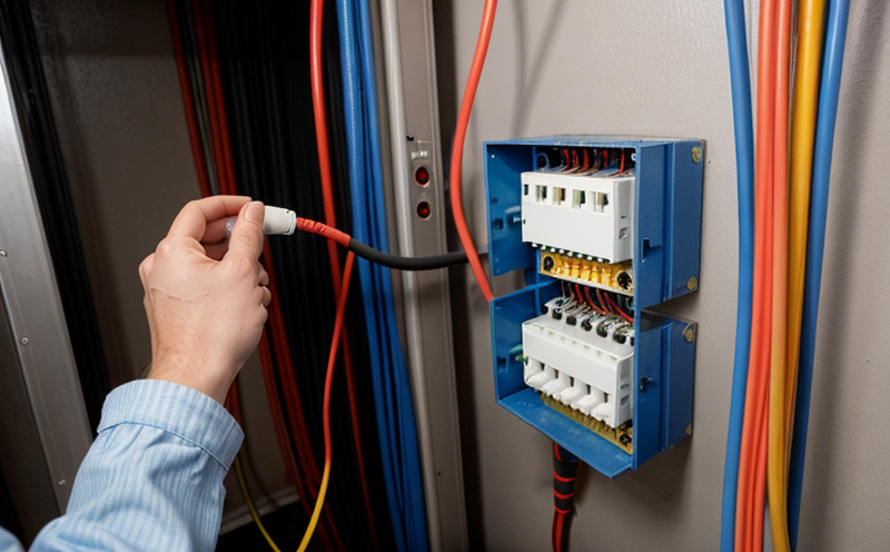
Visual Inspection
Before conducting any tests, inspect the cable and its components visually for signs of damage, wear, or corrosion. This includes checking the connectors, insulation, and conductor.
Use a multimeter: Measure the voltage drop across different sections of the cable to identify potential sources of signal loss.
Check impedance: Use an impedance meter to measure the resistance and reactance of the cable at various frequencies.
Measure capacitance: Use a capacitance meter to determine if there are any unwanted capacitive couplings between parts of the circuit.
Signal Integrity Testing
For more accurate measurements, consider using signal integrity testing tools that can analyze the high-frequency components of the signal:
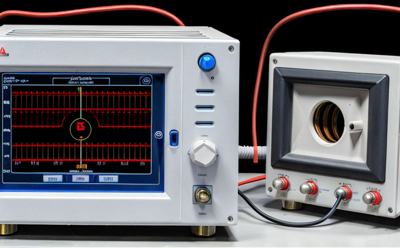
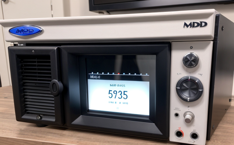
Vector Network Analyzer (VNA): A VNA measures the frequency-dependent impedance and reflection coefficients of the cable.
Time-Domain Reflectometry (TDR): TDR analyzes the reflections caused by changes in impedance along the cable.
Frequency Response Analysis: This tool measures the high-frequency response of the cable and identifies potential sources of signal loss.
Interference and Noise Reduction
In addition to testing for signal loss, its essential to minimize electromagnetic interference (EMI) and radio-frequency interference (RFI). Some common methods include:
Twisted Pair Cables: Twisting the conductors together reduces EMI by canceling out magnetic fields.
Shielded Cables: Using a shielded cable or wrapping the non-shielded cable with tape can reduce RFI.
Grounding and Bonding: Proper grounding and bonding of equipment and cables helps to reduce voltage differences that can cause signal loss.
QA Section
Here are some additional details and answers to frequently asked questions:
1.
What causes most signal loss in long cable runs?
Signal loss is often caused by a combination of resistance, inductance, capacitance, and dielectric loss.
2.
How do I measure signal loss in my long cable run?
Use a multimeter to measure voltage drop across different sections of the cable, and check impedance using an impedance meter.
3.
Can I use a regular oscilloscope for signal integrity testing?
No, for accurate measurements, use a specialized tool like a Vector Network Analyzer (VNA) or Time-Domain Reflectometry (TDR).
4.
Whats the best way to reduce electromagnetic interference (EMI) in my cable run?
Use twisted pair cables or shielded cables and ensure proper grounding and bonding of equipment.
5.
How often should I test for signal loss in my long cable runs?
Regularly inspect and test your cables, ideally every six months or when changes are made to the circuit.
By following these guidelines and using the right tools, you can minimize electrical signal loss in your long cable runs and ensure reliable operation of your industrial and commercial applications.